
Choose a briquetting layout by mapping how chips move through the factory. Alloy separation, collection effort and production continuity matter as much as press placement.
Which layout is better for your factory?
Centralized metal chip briquetting collects material from several machines at one processing area. Machine-side briquetting places equipment closer to a chip source or production cell. The better choice depends on alloy segregation, collection routes, production volumes and the available space.
Start by mapping material movement before choosing press size. A layout that appears compact on a drawing can still require frequent container changes, difficult access or unnecessary transport. Conversely, a central station may simplify supervision but need a carefully designed collection system.
Treat the two approaches as planning options. Final equipment suitability requires review of the actual chips and production conditions.
Map the chip streams first
List each production cell, the alloys it machines, its approximate chip output and how frequently the material changes. Record average production and busy periods separately. Include the current container route and who is responsible for collection.
Mark which streams must remain segregated. If chips from different alloys reach a common collection point, the layout needs a defined way to preserve identity. Briquetting changes physical form; it does not correct an unwanted alloy mixture.
Use a simple drawing with collection points, travel routes, storage and the proposed finished-briquette destination. Add access needed for maintenance and routine handling. Ask your site team to review the arrangement against local requirements before treating a floor-space estimate as final.
Compare the two arrangements
| Planning question | Centralized station | Machine-side or cell-based |
|---|---|---|
| Material collection | Evaluate transport from multiple sources | Evaluate short transfers near each source |
| Alloy segregation | Plan separate routes, batches or buffers | Preserve identification at each cell |
| Space | Reserve a shared processing area | Check available space around each cell |
| Service planning | Review the effect of one shared outage | Review access and service across multiple units |
| Expansion | Check collection and station capacity together | Check the requirements of each new cell |
These are comparison prompts, not guaranteed advantages. For example, fewer presses may reduce the number of service locations, while the central collection system introduces its own components and responsibilities.
A mixed approach is also worth assessing when one high-volume alloy stream behaves differently from the rest of the factory.
Size the complete flow, including buffers
Estimate how chips reach the proposed system during the working day. Simultaneous container deliveries can create a peak that differs from the average machining rate. Agree how much buffer storage is practical and how that storage preserves material identity.
Ask the supplier to review feed behavior, metering and any required preparation. Long tangled turnings should not be assumed to behave like short, flowable chips. The steel and cast-iron chip guide helps frame those material questions.
Include fluid collection and finished-briquette removal in the layout. If recovered fluid is considered for reuse, define its collection, assessment and treatment route separately. Keep responsibilities clear between the equipment supplier and the factory team.
Compare total project scope
Build an equipment-and-work list for each option: presses, collection containers or conveyors, feed buffers, preparation equipment where required, fluid handling, utilities and installation. Then add the expected collection tasks and service access requirements.
Use measured site information where possible. A shorter transport route does not automatically establish a labor saving; confirm what work is actually removed, who performs it and whether that time can be used elsewhere. Likewise, do not assume a central station eliminates all manual handling.
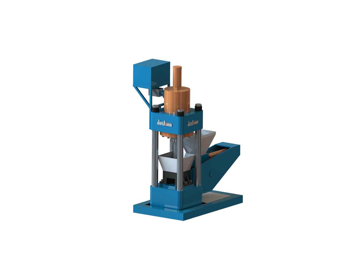
Review vertical briquetting presses and single-outlet configurations as part of the assessment. Confirm footprints, interfaces and capacity in the project proposal rather than inferring them from category photographs.
Review a horizontal briquetting layout or a short-chip lifting and tipping arrangement to identify the interfaces relevant to your collection plan.
Frequently asked questions
Is centralized briquetting always more economical?
No. Compare the complete collection and processing scope, production volumes, staffing tasks and installation requirements for your factory.
Can several alloys use one briquetting press?
Potentially, but material compatibility, segregation, changeover and downstream acceptance must be reviewed. A shared press does not remove the need for alloy control.
What should I send for a layout recommendation?
Send a floor plan, chip-source locations, alloy list, representative material photos, production volumes and the proposed briquette destination.
Discuss your project
Ask DerShan to review your briquetting layout. A material-and-flow brief helps define a practical configuration and identify the interfaces that need confirmation.
Technical references
Manufacturer references explain general equipment principles. Their model specifications and reported results do not describe DerShan equipment performance.